Grid / input AC
What is fixed about the incoming supply?
Frequency and waveform come from the utility side. The drive should not pretend those are free control knobs.
Analyzed a three-phase variable-frequency drive from AC rectification through DC-link energy storage and PWM inverter control.
Independent engineering analysis for Penn Hyperloop's recruitment process—not Hyperloop vehicle hardware. Maps 480 V three-phase AC through a diode rectifier, DC link, and PWM inverter so motor frequency/voltage control is understandable as a chain of energy conversions, with PWM carrier kept distinct from fundamental output frequency.
Engineering highlights
Motivation
What pulled me in, and what I wanted to get better at.
Why I built it
I started with limited intuition for how a variable-frequency drive actually turns fixed three-phase AC into controllable motor waveforms. I wanted a system-level map of every conversion stage and why it exists.
What interested me
The interesting part was the chain: rectify, store energy on a DC link, then switch that bus with PWM so the motor sees a controllable fundamental—not memorizing a block diagram.
What I wanted to learn
I wanted to separate PWM carrier frequency from fundamental output frequency, and to see losses, ratings, EMI, and protection as first-class design concerns—not afterthoughts once the motor spins in a slide deck.
System Overview
Independent engineering analysis for Penn Hyperloop's recruitment process. The write-up follows a three-phase VFD path from 480 V AC input through rectification, DC-link storage, PWM inversion, and variable-frequency output to a motor.
6-diode rectifier
Converts fixed three-phase AC into a unidirectional DC bus candidate.
DC link
Stores energy and smooths the rectified voltage for the inverter.
PWM inverter
Uses semiconductor switches to synthesize controllable three-phase AC from the DC bus.
Motor
Converts the synthesized electrical waveform into mechanical behavior.
Data flow
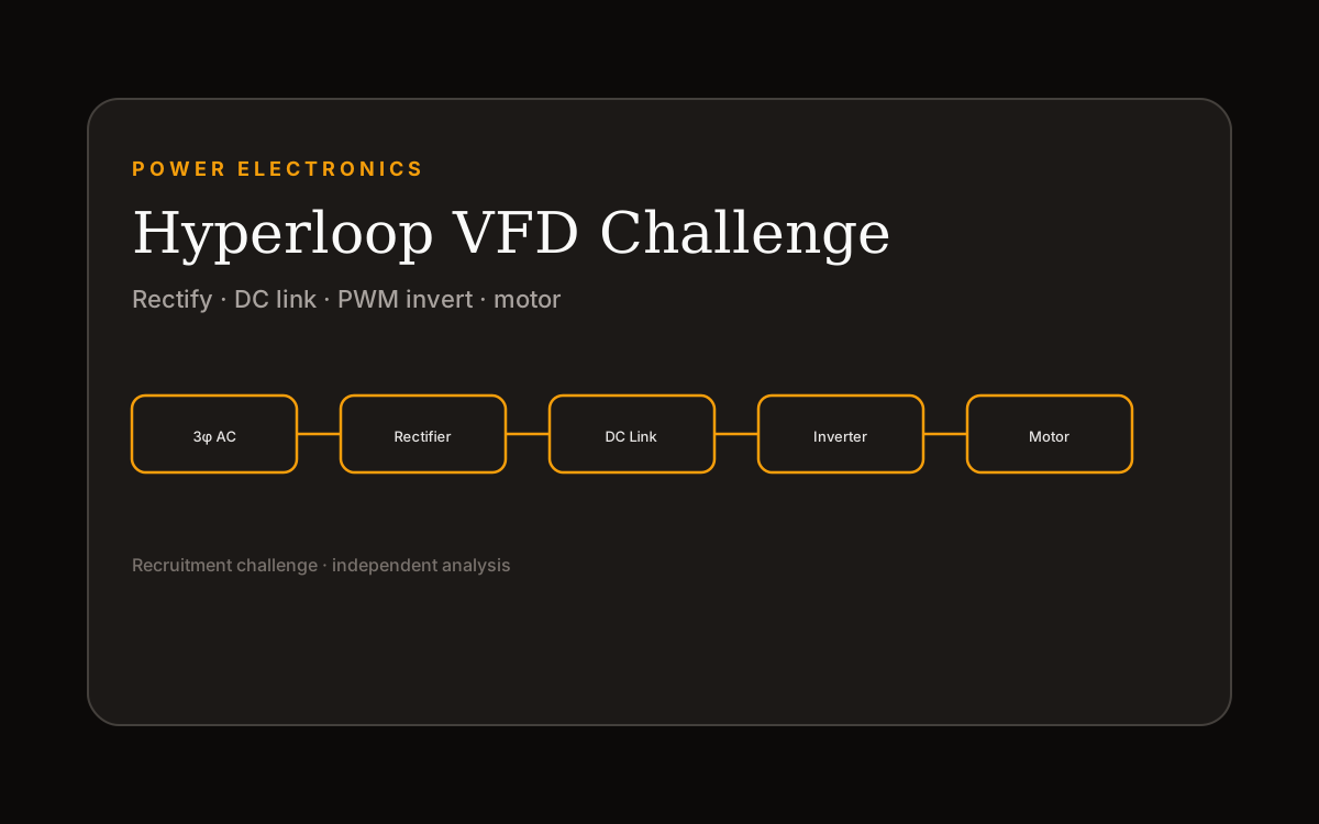
480 V 3φ AC → rectifier → DC link → PWM inverter → variable-frequency 3φ AC → motor.
Control flow
PWM commands decide switch states; switch states decide which DC rail each phase sees over time.
Design Challenge Deep Dive
Independent engineering analysis completed as part of Penn Hyperloop's recruitment process. Not hardware designed for or used on a Hyperloop vehicle.
Energy conversion chain
Grid AC is fixed. Rectification makes a DC bus. The inverter then switches that bus with PWM to synthesize controllable three-phase output for the motor.
Grid / input AC
What is fixed about the incoming supply?
Frequency and waveform come from the utility side. The drive should not pretend those are free control knobs.
DC bus
What do you gain by stopping at DC?
A stored energy reservoir the inverter can draw from while synthesizing a new AC waveform.
Inverter synthesis
How does control show up electrically?
Switch states and PWM decide the effective voltage/frequency content delivered to the motor.
Output frequency
Fundamental output frequency is strongly related to motor electrical speed.
Output voltage
Output voltage matters for magnetic flux and torque-producing behavior; it is not optional garnish on frequency control.
PWM ≠ fundamental
PWM switching frequency is the carrier / chopping rate. It is not the same thing as the fundamental frequency the motor uses for speed. Mixing them confuses both control and EMI conversations.
Switching states
A three-phase bridge connects each motor phase to either the DC+ or DC− rail. Hover or tap a state to see the educational current-path story.
U
V
W
Educational diagram · not a live simulation
U high-side and V low-side conduct; current leaves U and returns through V.
Switching losses
Every hard edge costs energy. Faster chopping is not free.
Conduction losses
On-state drops add heat even when switching looks gentle.
Thermal management
Losses that cannot leave the package become derating or failure.
Voltage / current ratings
Devices must survive bus peaks and motor current, not just average conditions.
DC-link ripple
A soft bus makes the inverter fight its own supply.
EMI
Fast edges couple into nearby control and sensor circuitry.
Switching frequency
Trades loss, audible noise, filter size, and EMI against control smoothness.
Motor current
Sets device stress, cable needs, and protection thresholds.
Protection
Overcurrent, overvoltage, and desat-style protections are part of the design, not a bumper sticker.
Engineering Breakdown
Each block covers the goal, the design, what broke, what changed, and what shipped.
Goal
Explain why fixed grid AC is rectified before motor control happens.
Design
Three-phase diode bridge into a DC link so later stages are not fighting the grid's fixed waveform directly.
Challenges
Iterations
Final implementation
Documented rectifier + DC-link roles as the front half of the VFD chain.
Goal
Show how six switches and PWM create controllable three-phase output.
Design
High-side / low-side bridge per phase, with PWM shaping the effective waveform while the fundamental sets motor-relevant frequency content.
Challenges
Iterations
Final implementation
Stage cards plus switching demo for intuition, not a full circuit simulator.
Key Design Decisions
What else was on the table, what I picked, and why it still made sense once the hardware was real.
The problem
Incoming grid AC has fixed characteristics; motors want controllable frequency and voltage relationships.
Alternatives considered
Tradeoffs
The extra conversion stages add semiconductors, capacitors, losses, and EMI work—but they buy waveform control.
Why I chose this
Use the DC bus as an energy buffer and let the inverter synthesize the motor waveform.
The problem
Switching rate and motor electrical frequency are easy to conflate when first learning VFDs.
Alternatives considered
Tradeoffs
Mixing the two makes speed/torque intuition and EMI/loss conversations fall apart.
Why I chose this
Treat PWM as the mechanism; treat fundamental frequency/voltage as the motor-facing command.
Evolution
Bench bring-up, CAD fits, soldering, and the demos in between. Not just the final photo.
Map
Forced every stage to answer what enters, what leaves, and why the stage exists.
Control
Linked abstract PWM talk to high-side / low-side conduction paths on a three-phase bridge.
System
Losses, thermal, ratings, ripple, EMI, and protection as first-class considerations.
Results & Validation
What worked in the end, what I can show for it, and where it's still limited.
Clear story from 480 V three-phase AC through rectifier, DC link, inverter, and motor.
Documented so motor behavior is not confused with switching rate.
Ratings and measured results are left as considerations / TODOs rather than fake datasheet claims.
Limitations
Reflection
What surprised me, what I'd redo, and questions I'm still chewing on.
What surprised me
What I would redesign
Future improvements
Questions that emerged